- 您现在的位置:买卖IC网 > Sheet目录3878 > PIC18F2431T-I/ML (Microchip Technology)IC MCU FLASH 8KX16 28QFN
PIC18F2331/2431/4331/4431
DS39616D-page 58
2010 Microchip Technology Inc.
PTCON0
2331 2431 4331 4431
0000 0000
uuuu uuuu
PTCON1
2331 2431 4331 4431
00-- ----
uu-- ----
PTMRL
2331 2431 4331 4431
0000 0000
uuuu uuuu
PTMRH
2331 2431 4331 4431
---- 0000
---- uuuu
PTPERL
2331 2431 4331 4431
1111 1111
uuuu uuuu
PTPERH
2331 2431 4331 4431
---- 1111
---- uuuu
PDC0L
2331 2431 4331 4431
0000 0000
uuuu uuuu
PDC0H
2331 2431 4331 4431
--00 0000
--uu uuuu
PDC1L
2331 2431 4331 4431
0000 0000
uuuu uuuu
PDC1H
2331 2431 4331 4431
--00 0000
--uu uuuu
PDC2L
2331 2431 4331 4431
0000 0000
uuuu uuuu
PDC2H
2331 2431 4331 4431
--00 0000
--uu uuuu
PDC3L
2331 2431 4331 4431
0000 0000
uuuu uuuu
PDC3H
2331 2431 4331 4431
--00 0000
--uu uuuu
SEVTCMPL
2331 2431 4331 4431
0000 0000
uuuu uuuu
SEVTCMPH 2331 2431 4331 4431
---- 0000
---- uuuu
PWMCON0
2331 2431 4331 4431
-111 0000
-uuu uuuu
PWMCON1
2331 2431 4331 4431
0000 0-00
uuuu u-uu
DTCON
2331 2431 4331 4431
0000 0000
uuuu uuuu
FLTCONFIG 2331 2431 4331 4431
0000 0000
uuuu uuuu
OVDCOND
2331 2431 4331 4431
1111 1111
uuuu uuuu
OVDCONS
2331 2431 4331 4431
0000 0000
uuuu uuuu
CAP1BUFH/
VELRH
2331 2431 4331 4431
xxxx xxxx
uuuu uuuu
CAP1BUFL/
VELRL
2331 2431 4331 4431
xxxx xxxx
uuuu uuuu
CAP2BUFH/
POSCNTH
2331 2431 4331 4431
xxxx xxxx
uuuu uuuu
CAP2BUFL/
POSCNTL
2331 2431 4331 4431
xxxx xxxx
uuuu uuuu
CAP3BUFH/
MAXCNTH
2331 2431 4331 4431
xxxx xxxx
uuuu uuuu
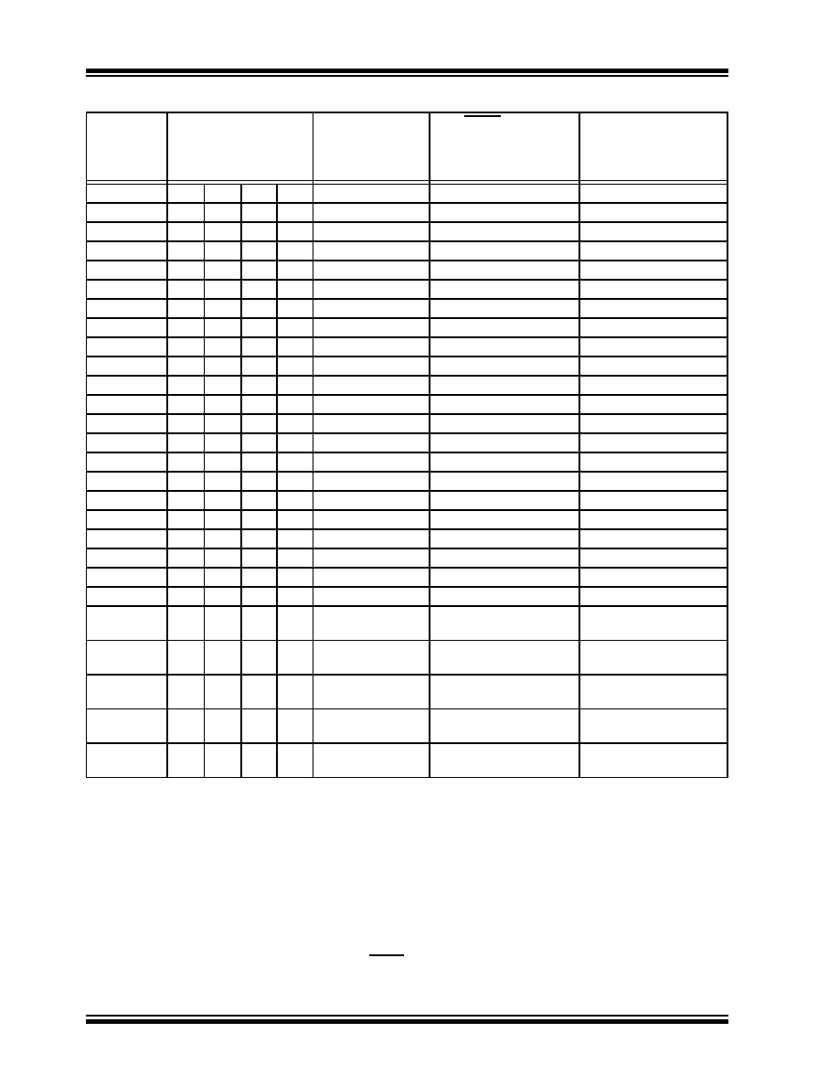
TABLE 5-3:
INITIALIZATION CONDITIONS FOR ALL REGISTERS (CONTINUED)
Register
Applicable Devices
Power-on Reset,
Brown-out Reset
MCLR Resets
WDT Reset
RESET
Instruction
Stack Resets
Wake-up via WDT
or Interrupt
Legend: u
= unchanged, x = unknown, - = unimplemented bit, read as ‘0’, q = value depends on condition.
Shaded cells indicate conditions do not apply for the designated device.
Note 1:
One or more bits in the INTCONx or PIRx registers will be affected (to cause wake-up).
2:
When the wake-up is due to an interrupt and the GIEL or GIEH bit is set, the PC is loaded with the
interrupt vector (0008h or 0018h).
3:
When the wake-up is due to an interrupt and the GIEL or GIEH bit is set, the TOSU, TOSH and TOSL are
updated with the current value of the PC. The STKPTR is modified to point to the next location in the
hardware stack.
4:
See Table 5-2 for Reset value for specific condition.
5:
Bits 6 and 7 of PORTA, LATA and TRISA are enabled depending on the oscillator mode selected. When
not enabled as PORTA pins, they are disabled and read ‘0’.
6:
Bit 3 of PORTE and LATE are enabled if MCLR functionality is disabled. When not enabled as the PORTE
pin, they are disabled and read as ‘0’. The 28-pin devices do not have only RE3 implemented.
发布紧急采购,3分钟左右您将得到回复。
相关PDF资料
PIC16LF1938-I/SO
IC MCU 8BIT FLASH 28SOIC
PIC16F639-E/SO
IC MCU FLASH 2KX14 20SOIC
PIC24F08KL402-I/SS
IC MCU 16BIT 8KB FLASH 28-SSOP
PIC16F1936-I/MV
IC MCU 8BIT 14KB FLASH 28UQFN
PIC16LF724-I/PT
IC PIC MCU FLASH 7KB 44-TQFP
PIC16F724-I/MV
MCU 7KB FLASH PROGRAM 40-UQFN
PIC16LF724-I/MV
MCU PIC 7KB FLASH XLP 40-UQFN
PIC18F2331T-I/SO
IC MCU FLASH 4KX16 28SOIC
相关代理商/技术参数
PIC18F2431T-I/MM
功能描述:8位微控制器 -MCU 16 KB FL 768 RAM 22 I/O RoHS:否 制造商:Silicon Labs 核心:8051 处理器系列:C8051F39x 数据总线宽度:8 bit 最大时钟频率:50 MHz 程序存储器大小:16 KB 数据 RAM 大小:1 KB 片上 ADC:Yes 工作电源电压:1.8 V to 3.6 V 工作温度范围:- 40 C to + 105 C 封装 / 箱体:QFN-20 安装风格:SMD/SMT
PIC18F2431T-I/SO
功能描述:8位微控制器 -MCU 16KB 768 RAM 22 I/O RoHS:否 制造商:Silicon Labs 核心:8051 处理器系列:C8051F39x 数据总线宽度:8 bit 最大时钟频率:50 MHz 程序存储器大小:16 KB 数据 RAM 大小:1 KB 片上 ADC:Yes 工作电源电压:1.8 V to 3.6 V 工作温度范围:- 40 C to + 105 C 封装 / 箱体:QFN-20 安装风格:SMD/SMT
PIC18F2439-E/SO
功能描述:8位微控制器 -MCU 16KB 768 RAM 22 I/O RoHS:否 制造商:Silicon Labs 核心:8051 处理器系列:C8051F39x 数据总线宽度:8 bit 最大时钟频率:50 MHz 程序存储器大小:16 KB 数据 RAM 大小:1 KB 片上 ADC:Yes 工作电源电压:1.8 V to 3.6 V 工作温度范围:- 40 C to + 105 C 封装 / 箱体:QFN-20 安装风格:SMD/SMT
PIC18F2439-E/SP
功能描述:8位微控制器 -MCU 16KB 768 RAM 22 I/O RoHS:否 制造商:Silicon Labs 核心:8051 处理器系列:C8051F39x 数据总线宽度:8 bit 最大时钟频率:50 MHz 程序存储器大小:16 KB 数据 RAM 大小:1 KB 片上 ADC:Yes 工作电源电压:1.8 V to 3.6 V 工作温度范围:- 40 C to + 105 C 封装 / 箱体:QFN-20 安装风格:SMD/SMT
PIC18F2439-I/SO
功能描述:8位微控制器 -MCU 12KB 640 RAM 21 I/O RoHS:否 制造商:Silicon Labs 核心:8051 处理器系列:C8051F39x 数据总线宽度:8 bit 最大时钟频率:50 MHz 程序存储器大小:16 KB 数据 RAM 大小:1 KB 片上 ADC:Yes 工作电源电压:1.8 V to 3.6 V 工作温度范围:- 40 C to + 105 C 封装 / 箱体:QFN-20 安装风格:SMD/SMT
PIC18F2439-I/SP
功能描述:8位微控制器 -MCU 12KB 640 RAM 21 I/O RoHS:否 制造商:Silicon Labs 核心:8051 处理器系列:C8051F39x 数据总线宽度:8 bit 最大时钟频率:50 MHz 程序存储器大小:16 KB 数据 RAM 大小:1 KB 片上 ADC:Yes 工作电源电压:1.8 V to 3.6 V 工作温度范围:- 40 C to + 105 C 封装 / 箱体:QFN-20 安装风格:SMD/SMT
PIC18F2439-I/SP
制造商:Microchip Technology Inc 功能描述:IC 8BIT FLASH MCU 18F2439 SDIL28
PIC18F2439T-E/SO
功能描述:8位微控制器 -MCU MCU CMOS 28 RoHS:否 制造商:Silicon Labs 核心:8051 处理器系列:C8051F39x 数据总线宽度:8 bit 最大时钟频率:50 MHz 程序存储器大小:16 KB 数据 RAM 大小:1 KB 片上 ADC:Yes 工作电源电压:1.8 V to 3.6 V 工作温度范围:- 40 C to + 105 C 封装 / 箱体:QFN-20 安装风格:SMD/SMT